The  -Mod
-Mod
English
Deutsch
It was a beautiful good day when 3Dsupply send me an email where they ask me whether I would not be glad to mod a
Speedpad. What for a question! But ago with it - immediately! A half week later we had the Pads already in our hands and we just begun a few thoughts to make
about how we could mod the pad. And that came out thereby:
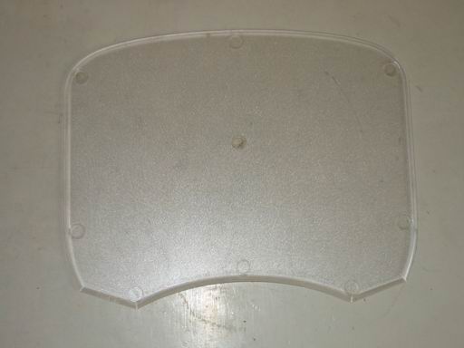
I already noticed the good sliding qualities when i unpacked the Pad. Hardly the
Pad was unpacked i had to play a little: the PAD tempts me to test it immediately under "real" conditions! And i didn´t play Quake for a long time... The
Pad is very well finished and very much ergonomic. One notices already: Made in Germany! (completely besides noticed: the Pad is built and designt around the
corner! Freiburg im Breisgau). This Pad can be used heedlessly also with a large monitor and high resolutions and for GREAT gaming by its
size. |
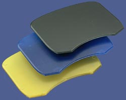 |
The corners of the PAD are rounded off and at the lower section cut something off at the heading. All edges are rounded beautifully smooth and don´t disturb the hand with rest upon. By the nine rubber feet and their perfect material the
Pad adheres almost everywhere behaviourless and is very skid-proof thereby.
Result: the speed Pad is ideally for the requirementful Gamer
who likes to take everything from its mouse. The price of 22,90€ becomes fair by the outstanding quality of workmanship. To refer with 3Dsupply.
4 pcs red 3 mm LED´s, 3000-5000mcd, 1,75V, 10-20mA
3 pcs. blue 3 mm LED´s, 1000-3000 mcd, 3,5V, 20-30mA
2 pcs. Resistors
(for fit with 4xred
about 320 Ohms, 3x blue about 60 Ohms)
something clear Tape and HotGlue
Dremel with 3 mm Drill
Soldering iron
Shear
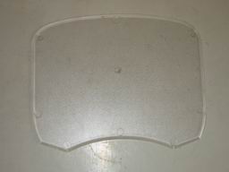 |
I don´t want to influence the outstanding sliding qualities of the Pads negatively somehow in no case with my Mod. Thus only a lighting was applicable from the
outside. In addition I snatched mine Dremel and drilled the Pad above. Altogether seven LED's should light up the Pad. I drilled the holes in the upper strip of the Pads. Drilling was not necessarily very simple: the
Pad is almost a little too narrowly. So the drilling with the 3mm drill into the Pad without frays or tears the holes was difficult. But finally
everything is fine and hotglue makes all looks well * g *. |
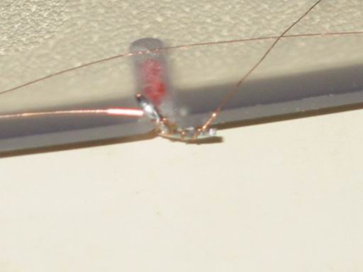
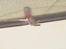
| Then the soldering: I first attached the red LEDs in series together. Then the
blue ones. Unfortunately it cost me an LED during the short test run. An other red one was quite a bit lower in brightness than the other ones
(look at the the photo at the bottom left hand corner). The second start ran already better: I attached and with pre-resistor provided the LEDS
parallel in each case after the colour. Now all light up in the correct intensity and hopefully dont get broken any more. I soldered the LEDS on by using
copperlacquerwire. This does not lay on very thickly and I can I glue it easily with Tape on the rear
side. |
 |
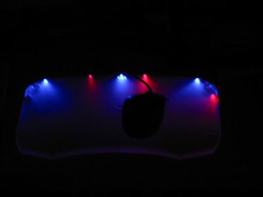
I solderd then the four wires of the LED to a stronger inlet and into the Cinch plug (at the housing I have
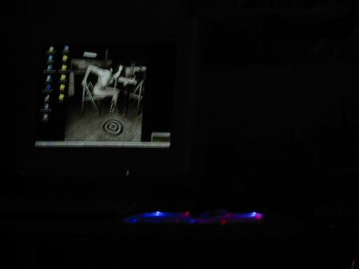
fastened a Cinch socket to the current supply) Then i soldered the resistors. Finished. Attached and see there: the desired effect is operational! Here still another
few.
Happy modding,
hartwareguru